The Construction Style you select for your Construction Method is very important. This selection determines the Parts available for your Construction Method as well as options within each Part that are specific and necessary for the Style of Construction you need to configure. There are 5 possible Case Construction Styles:
Face Frame
A face frame in cabinet making is the frame fixed to the front of a cabinet carcass which obscures the edges of the carcass and provides the fixing point for doors and other external hardware. A face frame provides strength to the front of a cabinet and is also considered a visual feature of particular styles of furniture. In CABINET VISION selecting the Face Frame Style turns on the Face Frame Branch and its Parts in the Construction Method. Door Sizing for this Construction Style is controlled by the Hinge Overlays in the Material Manager.
Frameless
Frameless construction in cabinetmaking refers to the construction of cabinets using flat panels of engineered wood, usually particle board, plywood or medium-density fiberboard, rather than the traditional frame and panel construction. Frameless cabinets typically make use of edge banding to conceal the edge of the carcass. This is most commonly seen in European modular-style kitchens. In CABINET VISION selecting the Frameless Style turns off the Face Frame Branch and removes the Machining options from the Construction Method. Door Sizing for this Construction Style is controlled by the Reveals within the Exterior Case Branch.
32 Millimeter
Is the same as the Frameless Construction Style visually. In CABINET VISION selecting the 32mm Style turns off the Face Frame Branch and turns on the Machining options from the Construction Method. Door Sizing for this Construction Style is controlled by the Reveals within the Exterior Case Branch.
Frame Overlay
Is the same as the Face Frame Construction Style with the exception that Doors are sized by the Reveals rather than the Overlays. This allows you to give the look of European Cabinetry (Frameless/32mm) with the added strength of the Face Frame. In CABINET VISION selecting the Frame Overlay Style turns on the Face Frame Branch and its Parts in the Construction Method. Door Sizing for this Construction Style is controlled by the Reveals within the Exterior Case Branch.
Closet 32mm
Is similar to the 32mm Style with the exception of the addition of Parts in the Construction Method specific to Closets. Door Sizing for this Construction Style is controlled by the Reveals within the Exterior Case Branch.
Typically, you would want to name your Construction Method something that indicates its contents, for example: If you only have one Face Frame Construction Method, then the name "Face Frame" would suffice. However, if you have several Face Frame methods, then your names should be more descriptive like "Face Frame No Back," or "Face Frame Dado Back." Since Style determines Door Sizing this is a very important selection.
The Branches
Following are the available Branches in an Assembly Construction Method:
Face Frame
Interior Case
Exterior Case
Operations
Connection
How to Create a New Construction Method
There are several ways to begin a new Construction Method. You could start with one of the Construction Methods that are pre-set in CABINET VISION and make modifications to them. You could copy one of the existing Construction Methods and then make changes to the copy so that it meets your requirements. Finally, you could create a brand new Construction Method by clicking on the Create a New Construction Method button (or by clicking on the Construction menu at the top of the Assembly Manager window and then clicking Create New Method). For the purposes of this example, we will create a brand new Construction Method because the options will be the same.
1. Click the Create New Construction Method option in the ribbonbar. 
2. In the pop up window, give the Construction Method a name and select the Construction Style that should apply to this Construction Method. You should also select the Connection Machining to use for the options in the Connections area. Connection Machining is configured through the Connection Manager.
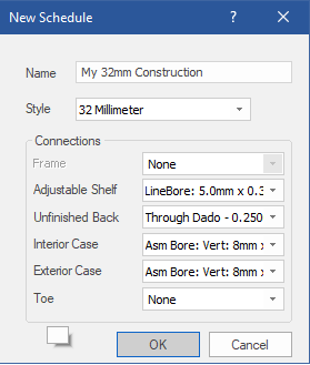
3. When you click OK, you will see the following window. Notice that the name of the Construction Method is "My 32mm Construction" and the Construction Style is 32 Millimeter.
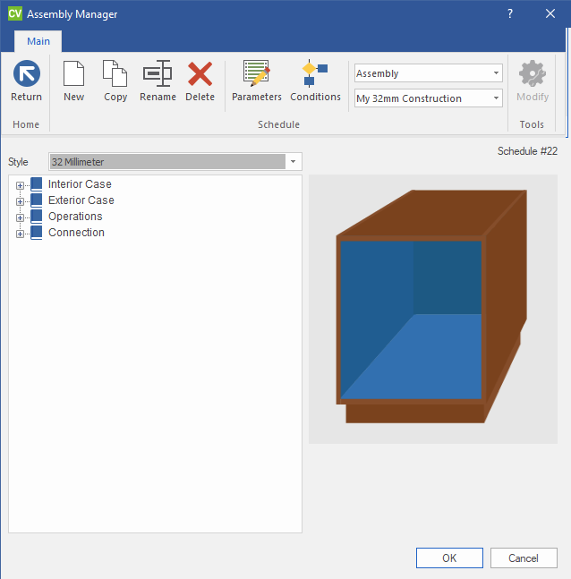
4. Next, you should begin to run through the Assembly Manager and answer the questions in each section. Start by clicking on the + symbol next to Interior Case and then double clicking Adjustable Shelf. Double clicking on a branch (such as Adjustable Shelf) runs the Part Wizard for that branch. You can also run the Part Wizard for a branch by clicking the branch to select it and then clicking the Modify option in the ribbonbar. You will then see the following window:
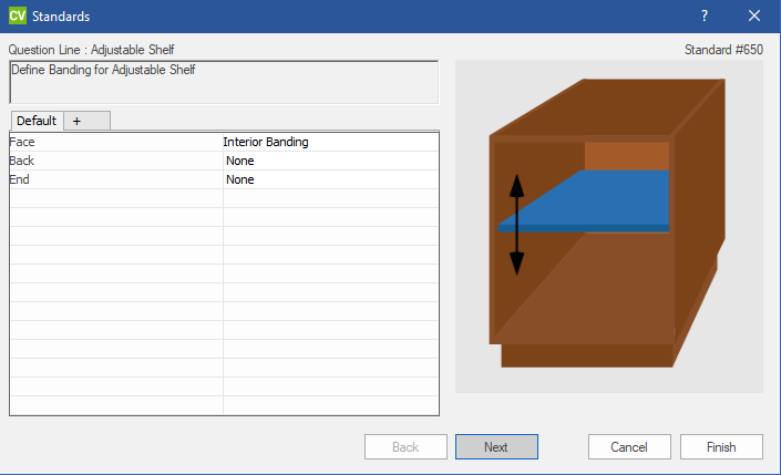
The Assembly Manager consists mainly of options that you may choose between. In our example, the first option that you must configure concerns Adjustable Shelf banding.
 You will find that the illustrations can be very helpful tools when answering the Assembly Manager questions. The illustrations will change according to the choices that you make and they should give you an idea of what will happen in the Construction Method if certain choices are made. However, you should not be worried if the pictures don't match your Construction 100%. Simply choose the options that most closely resemble your Construction Method.
Break Outs
When answering questions in the Assembly Manager, you will notice that you are configuring the "Default" which applies to all Cabinet Classes. You might however for some reason need to Break Out the question if a different Class object needs a different configuration.
Example of the use of a Break Out:
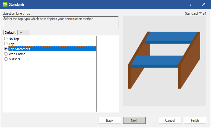
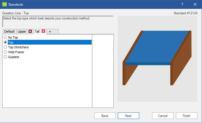
A classic example of the need to add a break out is when the Top type is different between Base Cabinets and Upper and Tall Cabinets. In this example, we use Stretchers in Base Cabinets and a full Top in the Upper and Tall Cabinets.
In order to define a different configuration for other Class objects simply click the + Tab next to Default then select the Class you need to define a different Configuration for.
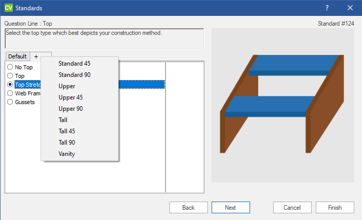
In this case i have selected Upper and Tall in order to specify full Tops for them.
5. Then, simply go through the rest of the questions by answering them and then clicking Next. When you answer the final question in the branch, you will need to click the Finish button.
6. When you finish the questions for the first branch, move on to the next one and answer the questions there.
7. Complete the rest of the Branches for this Construction Method adding break outs for any situations that require it.
8. Test your Construction Method in a Job. The easiest way to begin testing a Construction Method is to create a Job with a single Cabinet. Start out with a single Base Cabinet in the Job making sure that the overall size of the Cabinet is one that you can easily work out a cut list for comparison. Also make sure that you are using a valid Material Schedule for this Job and that each part of the Cabinet is made out of the correct Material.
Part thickness, which has a huge influence on the cut list, is controlled by the Material Schedules and NOT the Construction Method. Check each Part of this test Cabinet and make sure that it is sized correctly. For any Parts that are incorrect, try to look at the orthographic views to determine where the problem lies.
Next, put a second Base Cabinet next to the first one. Each Cabinet should now have an Unfinished End and other properties that go along with a Cabinet next to another Cabinet.
Follow the same procedure for Upper Cabinets, Tall Cabinets, Vanity, and finally Corner Cabinets.